| Forum Archaeologiae - Zeitschrift für klassische Archäologie 37 / XII / 2005 |
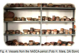
The work presented in this article shows the results about symmetry and unwrapping of decorations of NASCA ceramics in-situ using a 3D-Scanner. First we show the results of the estimation of the profile line of NASCA sherds using the method developed for ceramics manufactured on rotational plates. Than we show analysis regarding the manufacturing process of NASCA ceramics and a method for unwrapping painted ceramics. Figure 3-4 shows examples of the acquired sherds and vessels. Finally a conclusion and an outlook are given.
Sherds
Regarding the overlay of multiple profiles, the rotational axis has been found properly, because the variation between the profile lines is less than 5 mm. In case of a wrong rotational axis the variation of multiple profile lines would be more than 10 mm. Therefore the positioning of the sherds is geometrically correct. For evaluation of the automatically estimated profile
Defined by the estimated axis and a list of angles, multiple planes are estimated. The list of angles can be adapted manually or automated. For general applications in archaeology one angle, at the highest point of the sherd is sufficient. For complex breakages certain points on the surface and therefore angles can be set to estimate a virtual longest profile line. For analysis of the symmetry and for this report we used an arbitrary list of angles between 0° and 355°, with a stepping of 5°. Figure 5 shows multiple profile lines, the longest profile line and the profile line at the highest point of vessel 2801-V3.
To determine the excentricity of a vessel we divide it into horizontal slices of 10mm, which approximates the height of one layer of clay shaped by human fingers. For each layer we estimate a rotational axis. For each axis the tilt-angle a towards the overall rotational axis is estimated. Because of distortions in the layers of the flat bottom area and thin orifice area, only angles a from the main section of the vessel are estimated. Table 2 shows the vessels sorted by the average of α.
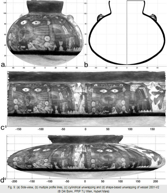
In respect to manual drawings of painted objects, we can also estimate unwrapped paintings using a mixture of the shape-based and cylinder-based method.
Acknowledgement
Introduction
The Kommission für Archäologie Außereuropäischer Kulturen (KAAK) of the German Archaeological Institute (DAI), in Bonn is conducting an investigation project about the pre-hispanic occupation of the Palpa Valley, Peru. During the field-trip in 2005 we brought the 3D-Scanner of the Faculty for Informatics of the Vienna University of Technology to Palpa. Aim of this cooperation was to test the possibilities for documentation of freehand manufactured ceramics by using a 3D-Scanner.
The ceramics for our experiments are from the Nasca-period (200 B.C.-650 A.C.) [RI01]. This material seemed most appropriated for our intentions: During the last nine years of excavations by the KAAK several thousands of sherds of this period had been recovered from stratigraphic contexts, as well as some hundred complete vessels from gravelots. Analysis of the Nasca ceramics from Palpa is in process and so is the documentation of the material. The main question of analysis is concerned to the chronology of the Nasca culture. As recent fieldwork has shown the existing relative chronology of Nasca ceramics is in urgent need of revisal [RI01; SP02]. The possibility of automated documentation by using a 3D-Scanner is of great interest for the purpose of accurate and fast documentation of the material.
For chronological analysis of Nasca ceramics the decoration of the vessels is of supreme interest. About 40% to 60% of the findings are decorated fine-ware. The complex decoration themes allow to make sharp stylistic distinctions witch are together with the vessel shape the main clues to chronological ordering of the material. For the documentation of decorated sherds the applicability of the method of automated acquistion to ceramics manufactured without using rotational plates has to be tested. Even more time consuming is the hand-drawing of complete decorated vessels. Specially therefore the use of a 3D-Scanner promises accurate and fast results as compared to hand-drawing.
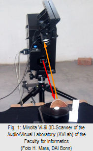
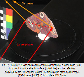
Furthermore, the high-resolution (< 1mm) of a state-of-the-art 3D-Scanner allows the estimation of features regarding the manufacturing process, which is reflected in the symmetry of an object. Analysis of symmetry might help to better understand the manufacturing process of Nasca ceramics [PC86] and solve the ongoing discussion on the use of rotational plates [WT02, AM83] in South America. Comparison of vessel forms by exactly measured form and symmetry might lead to answering further going questions on social, economical and political organization of past society. The acquisition was done using a Minolta Vi-9i 3D-Scanner based on the principle of structured light [KL96], which is shown in Figure 1-2.

For our first experiments we acquired 38 sherds found in the area with locus number 824. These sherds were used to test the estimation of the axis of rotation using a circular template matching [MS05] on NASCA sherds, because this kind of ceramic is not supposed to be manufactured on rotational plates, but they appear to be rotational symmetric.
Table 1 shows three typical results for sherds, which belong to the same object or type of object (bowl). The left column shows the front-view as a grayscale image. The original images of the 3D-Scanner are color images, but due to improper illumination, the colors are distorted. Therefore the images have been reduced to grayscale, which is also used for publication. The right column shows overlaid multiple profile lines, which have been extracted every 5°.

Sherd 824-4

Sherd 824-4b
Sherd 824-157
Table 1: left column: sherds, right column: profile lines
 line, archaeologists compared these profile lines, with profile lines of well-known, complete vessels of the same type. In case of the sherds with finding number 824-4, 824-4b and 824-157, the corresponding vessels are bowls like shown in Figure 5.
Therefore we classified the results of the automated profile line into three groups. The first group are correct profile lines, where the manual drawings match the automated profile line. The second group are valid profile lines, where the automated profile line match profiles of similar vessels, but not the manual drawing. The third group are automated profile lines that match no related vessel.
For our example shown in Table 1, we could determine that 824-4b is correct, 824-157 has a valid orientation and 824-4 is incorrectly positioned, because such bowls are similar to cone segments with a bottom diameter smaller than the rim-diameter.
These results show that Nasca ceramic has not been manufactured on rotational plates. The automated orientation of these sherds does not work because the vessels are not sufficiently symmetrical to the rotational axis. For the following step we choose to acquire complete vessels, where the complete geometry is preserved for analysis regarding the manufacturing process. The next section shows our experiments regarding complete vessels.
Vessels
For our analysis regarding symmetry of NASCA ceramics, we acquired 102 complete vessels found during the excavation seasons 2003 and 2004. Additional 20 vessels have not been acquired, because they were special finds (e.g. figures) and therefore not relevant for the validation of the chronology applied to fine and coarse ware. For each vessel 4 2˝D-Images of the wall of the objects and 1 to 3 2˝D-Images of the bottom were acquired to estimate a complete 3D-Model.
The supposed axis of rotation of the 3D-model has been estimated by fitting circle templates into horizontal cross-sections in the same way as it is estimated for sherds [MS05]. To find the orientation for horizontal intersections the orientation of the object on the rotational plate is used as first approximation, which is iteratively optimized. Even though these cross-sections can be elliptic; the center of the fitted circle is located between the two foci of the ellipse. Therefore a line is fitted through the circle centers and assumed to be the rotational axis. Figure 6 shows the horizontal intersections of the vessel 2801-V3 (circular) and 2827-V1 (elliptic).
Nr.
Finding Nr.
avg(α)
max(α)
1
2801-V3
1.0
2.4
2
2240-V1
1.4
2.9
3
2245-V3
1.6
2.1
4
1919-V1
1.6
7.3
5
1919-V2
2.3
12.6
6
1776-V2
2.3
5.6
7
2813-V2
2.4
3.3
8
2216-V1
2.8
7.7
9
2351-V1
3.3
14.9
10
2830-V5
3.4
8.8
11
2801-V2
3.9
11.0
12
1902-V1
4.3
11.1
13
1919-V3
5.6
14.6
14
2827-V1
5.8
18.5
15
2354-V1
7.6
27.4
16
2260-V1
11.9
33.1
17
2316-V1
12.0
35.8
Table 2: Average and maximum tilt angle a of rotational axes of sub segments towards the overall rotational axis
 Figure 8 shows a plot of the average and maximum angle of Table 4, where we could determine an increase of the angles for the last four vessels.
The result of the acquisition and processing of vessels using a 3D-Scanner are a data-sheet showing views of all sides (front, left, right, back), the longest profile line, multiple profile lines (as shown in Figure 7) and horizontal intersections (as shown in Figure 6). The horizontal intersections are used to estimate the angle a as quality criteria. Furthermore we estimate an unwrapped image of the painting of the decorated vessels. Such documentation can be estimated in less than two hours. The acquisition itself requires less than half an hour per complete vessel. Therefore it is possible to acquire vessels in-situ in a fraction of time than compared to the manual drawings. The remaining time for documentation can be done in a remote location. The next section shows examples for the unwrapped paintings.
Texture Unwrapping
As the 3D-Scanner acquires an image (photo) for each 2˝D-Image, these images are used as texture map for the 3D-Model. Archaeologists traditionally transfer these drawings manually into planar drawings, which requires between one and two working days. Therefore we can assist them by estimation of an unwrapped painting. An example is shown in Figure 9 for vessel 2801-V2. This vessel can not be unwrapped without distortion of the painting. Therefore, we show two different ways of unwrapping the paintings. The first method is an unwrapped painting projected on a cylinder as shown in Figure 9c. The second method is based on unwrapped painting using the shape of the vessel (shown in Figure 9d).
Conclusion & Outlook
Estimation of the traditional longest profile lines and horizontal intersections gives archaeologists new, objective means of analyzing the chronology of ceramics by surveys of changes in quality and shape. We have shown the extend application of 3D-Scanners by estimation of unwrapped paintings, which require a fraction of working time in respect to traditional, manual documentation.
For future work, we are proposing an automated estimation of classification rules, which will assist archaeologists to classify new findings, validate and enhance existing rules using databases of profile lines. This estimation of classification rules will be based on comparison of profile lines using PCA [IJ02], which has been used for analysis of shapes (profiles) changing over time for medical application [KPLB04, LPB05].
· Projekt "Naturwissenschaftliche Technologien in den Geisteswissenschaften (NTG) of the German Government under supervision of Markus Reindel, DAI Bonn, for partially funding the travel expenses and for funding the transport of the 3D-Scanner.
http://www.dainst.org/index_593_en.html
· Technical University of Vienna, Faculty of Informatics, Austria under supervision of Robert Sablatnig for providing the 3D-Scanner of the Audio/Visual-Laboratory.
· PRIP Club for partially funding the travel expenses.
http://club.prip.tuwien.ac.at
· PRIP Advanced Video Lab.
http://www.prip.tuwien.ac.at/avlab/
References
[RI01] M. Reindel und J. I, Cuadrado, Los Molinos und La Muńa. Zwei Siedlungszentren der Nasca-Kultur in Palpa, Südperu, In Beiträge zur Allgemeinen und Vergleichenden Archäologie 21, Mainz: Philipp von Zabern 2001.
[SP02] H. Silverman and D. Proulx, The Nasca, Malden/Oxford: Blackwell 2002.
[PC86] Patrick H. Carmichael, NASCA Pottery Construction, In Nawpa Pacha, Volume 24, Berkeley, California, 1986.
[WT02] A. Wieczorek and M. Tellenbach (eds.) 2002: An die Mächte der Natur - Mythen der altperuanischen Nasca-Indianer. Katalog zur Ausstellung im Reiss-Engelhorn-Museum. Mainz: Philipp von Zabern. Darin: Exkurs zur Frage der Drehscheibenkeramik S. 54-63.
[AM83] Arthur M. Sackler Fundation, The Art of the Andes: Pre-Columbian Scupltured and Painted Ceramics from the Arthur M. Sackler Collection, 1983.
[KL96] M. Kampel and Ch. Liska, Keramik und Laser, Forum Archaeologiae 6/III/98 (http://farch.net).
[MS05] H. Mara and R. Sablatnig, 3D-Vision Applied in Archaeology, Forum Archaeologiae 34/III/2005 (http://farch.net).
[IJ02] I. T. Jolliffe. Principal component analysis. Springer, 2002.
[KPLB04] F. Kainberger, P. Peloschek, G. Langs, K. Boegl, H. Bischof, Differential diagnosis of rheumatic diseases using conventional radiography, in Best Practice & Research in Clinical Rheumatology 2004 December, 18(6):783-811. (Elsevier), PMID: 15501183 [PubMed - in process].
[LPB05] G. Langs, Ph. Peloschek, H. Bischof, Optimal Sub-Shape Models by Minimum Description Length, in Proceedings of IEEE International Conference on Computer Vision and Pattern Recognition CVPR 2005, San Diego, USA, Vol. 2, pp. 310-315.
![]() © Hubert Mara, Niels Hecht
© Hubert Mara, Niels Hecht
e-mail: mara@prip.tuwien.ac.at, nihecht@web.de
This article should be cited like this: H. Mara - N. Hecht, Analysis of Geometry and Documentation of NASCA Ceramics using 3D-Acquisiton, Forum Archaeologiae 37/XII/2005 (http://farch.net).