| Forum Archaeologiae - Zeitschrift für klassische Archäologie 96 / IX / 2020 |
In this paper we present and compare two separate wood-firings of predominantly plain, handmade burnished ceramics in an updraft kiln. Our main aim was to gain a better understanding of the function of the kiln and a greater knowledge of ancient firing processes. Both firings took place in the same kiln, but the pottery installation underwent a series of modifications and the fuel type was partially changed for the second firing [1]. The objectives of the experiments were to: a) evaluate the effectiveness of the kiln based on the heat rate, the maximum temperature achieved, and heat loss, b) investigate the effect of the fuel type on heat efficiency, c) assess the impact of the temperature and prevalent atmosphere on the colour and texture of the pottery, and d) check the quality of the fired vessels and, if necessary, provide more sophisticated adaptations to improve the heat efficiency of the installation.
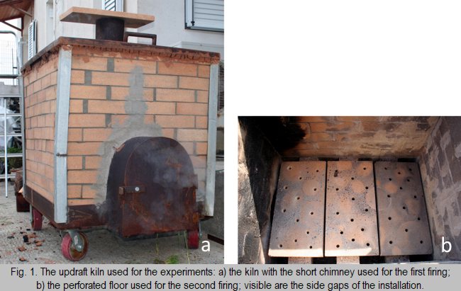
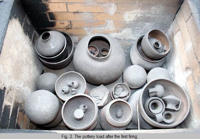
The updraft kiln type is a two-chamber, vertical installation where the fuel is separated from the pots and the hot air flows from the lower to the upper chamber (Conway 1976, 92; Dawson and Kent 1984; Prillwitz and Hein 2015; Thér 2004, 39–40; Zakin 2020, 5–6). During the experiments, the pottery was placed in the upper chamber (0.85 x 0.60 x 0.48m), while the lower combustion chamber or ‘fire box’ (0.85 x 0.60 x 0.29m) was used to stoke the fire. Between the two chambers, three adjacent fire plates (0.25 x 0.50 x 0.04m) constituted the floor upon which the pots were stacked. For the second firing the original compact fire plates were replaced by thinner ones (0.03m thick) that were perforated with evenly distributed vents, each with a diameter of 0.012m (Fig. 1b). Along the long sides of the walls, between them and the pottery chamber floor, a gap (0.06m in width) allowed the hot gases and flames to pass directly from the fire box into the upper chamber (Fig. 1b). This gap was 0.03m wide at the transverse sides. For an overview of the main modifications to the kiln, as well as the changes in atmospheric conditions and the fuel types used in the two firings, see Tab. 1.
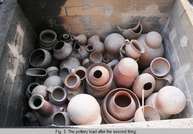
The pottery chamber in both firings was less than half-full (Figs. 2 and 3), with more available space between the vessels in the first firing compared to the second. The larger vessels were put directly on the floor of the chamber. Occasionally, medium- or large-sized pots with convex bases were placed upside down. It is noteworthy, that several pots near the side walls were resting partly or directly on the gap. For the first firing, the pots were stacked in columns, one upon the other in a vertical arrangement (Fig. 2) [4]. The drinking cups and the miniature vessels were often put inside the larger pots. In the second firing, the pots in the front part of the chamber were piled in a lattice-style arrangement (Abu-Ziyan 2004) (Fig. 3). However, the vessels in the middle and the back parts of the chamber were stacked one above the other in columns. The columns were close to each other, leaving narrow passages for the hot air and gases to circulate [5]. In contrast to the first firing, the bulk of the drinking cups were put in the upper parts of the load and not in the interior of the larger vessels.
3. The firing process
3.2. The second firing
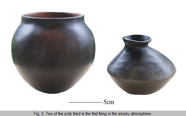
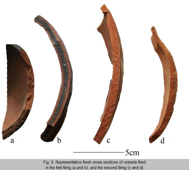
Nevertheless, it is worth noting that there were difficulties in spreading the fuel and the charcoal into the front corners of the kiln close to the stoking channel. This was the case in both firings. In general, the hot air and gases did not circulate evenly and sufficiently throughout the pottery chamber. It was found that the interiors of the vessels that had been placed upside down were fully oxidised in both firings. The surface colour of the majority of the vessels in the first firing was uniform, although there were exceptions. The deliberately induced smoky atmosphere created surfaces that were black or black with a dark brown shade on those vessels manufactured from the Chalkis clay, and dark grey or greyish/black surfaces on those made from the Cretan clay (Fig. 5). The fresh cross sections of the vessels of both types of clay usually appeared fully oxidised brown (Fig. 6a), but the sections of the thicker-walled vessels made from the Cretan clay occasionally displayed a grey or black core (Fig. 6b).
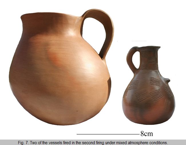
In the second firing, the vessels situated in the middle and back parts of the chamber were either homogeneous in colour or displayed patchy discolorations (Figs. 3 and 7). It would appear that mixed conditions (oxidising and reducing/under-oxidising) prevailed in these parts of the upper chamber. Generally, those vessels made from the Chalkis clay, which were situated in the middle and back of the kiln, were orange, orange brown or, occasionally, dark orange, and often exhibited black shades (Fig. 7). In the same parts of the kiln the small number of vases made from the Cretan clay became brown. Those parts of the pots that rested just above the side gap consistently appeared pale greyish brown, implying under-oxidising conditions during firing. On the other hand, those vessels loaded in the front part of the kiln consistently displayed dark, almost black surface colours due to the prevailing smoky atmosphere throughout the cooling stage (Fig. 3). The fresh cross sections appeared uniform – either brown for pots placed in the front part of the kiln, or orange brown and orange for those in middle and rear parts (Fig. 6c). However, some examples also showed light greyish-brown external margins, which were usually associated with vessels located next to the side gap (Fig. 6d).
For further investigation of the firing atmosphere and a basic estimation of the temperature reached in the second firing, comparisons were made with a set of test sherds. These sherds were prepared from the same types of clay as the vessels that were fired in the updraft kiln. The test sherds were fired in an electrical furnace under controlled oxidising conditions at different temperatures (600°C/1h, 700°C/1h, 800°C/1h, 900°C/1h, and 1050°C/1h) so that the full colour development could be documented [7]. The comparison of the vessels with the test sherds confirmed that the orange colour or the orange shades of several of the vessels were indicative of higher temperatures at the back and central parts of the kiln. Furthermore, the dark orange colour suggests that the achieved temperature was often higher at the bases of those vessels situated directly on the perforated floor [8]. The same applies to the adjoining parts of the neighbouring vessels. Three reference sherds situated at the uppermost back part of the kiln above the side gap in an inclined position exhibited fireclouding and sooting (Rice 1987, 235).
1. The kiln
We used a rectangular, wood-fired kiln for our experiments (Fig. 1a). The entire structure was placed on wheels to make it movable. The kiln walls were built from a layer of firebricks (0.11m in thickness), while the stoking channel and its door, as well as the cover and the chimney, were all made of iron. Slight deformations on one of the two long sides were observed after the first firing, so the corners of the installation were supported with additional elongated metal sheets for the second firing.
First firing
Second firing
Chimney height
0.30m
2.30m
Top of chimney
Closed (after reaching the maximum temperature)
Open (constantly)
Pottery chamber floor
Compact fire plates, 0.04m in thickness
Perforated fire plates, 0.03m in thickness
Firing atmosphere
Smoky (in the final stage of firing)
Mixed (in the final stage of firing)
Kind of fuel
Chopped pine wood; small olive logs, 0.08-0.10m in diameter; fresh grass after the maximum temperature was achieved
Chopped pine wood; twigs from olive and orange trees, complementary brushes of vine; brushwood and dried leaves in the advanced stage of firing; fresh grass after the maximum temperature was achieved
Tab. 1. Overview of the main changes between the two firings.
The fuel was added through a short stoking channel (0.25 x 0.35 x 0.42m), which faced north during both firings. The top of the channel extended 0.03m above the top of the combustion chamber. The stoking hole had a door for stopping sudden airflows, thus preventing the fire from rapid, unwanted temperature rise. This also worked as a means to regulate the air supply and draft, and helped to raise or reduce the temperature when desired. A central, cylindrical chimney (0.15m in diameter and 0.30m in height) was attached to the cover that closed the upper part of the kiln (Fig. 1a). The chimney was extended by two metres for the second firing. During firing, the temperature was determined by a thermocouple that was placed in the middle of the back wall of the pottery chamber.
2. The pottery load
The shape, surface treatment and forming techniques for the majority of the pots used in the experiments were inspired by extant examples of prehistoric pottery, mainly found in Greece and the surrounding region, including Cyprus (see facebook.com/JasperHandmadeCeramics).
A number of different handmade manufacturing techniques were applied for building the pots. It should be stressed that the vessels used in both firings comprised of a range of shapes, sizes, and wall thicknesses, although the vast majority were thin-walled and medium-walled. All vessels were burnished and had a highly glossy appearance. A few pottery sherds were also fired during the second firing. These constitute part of a reference collection produced by G. Kordatzaki, and are representative of a wide spectrum of manufacturing techniques. Besides being burnished, the reference sherds were also polished and smoothed [2]. The bulk of the ceramics in both firings were made from similar clay pastes, whereas very few pots were prepared from other types of commercial clay. Specifically, two different, semi-fine types of clay from Greece were used, including a commercial one from Chalkis, pale brown when unfired, and a non-commercial clay from central Crete that is dark grey in its raw state [3].
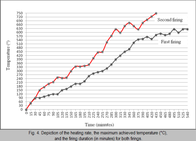
In order to avoid a rapid temperature rise in the early stages of the firing process, the fire was kept at the mouth of the combustion chamber during both firings. The slow increase in temperature up to 200–250°C prevented potential damage to the pots due to water evaporation during the water smoking stage (Fig. 4) (Rye 1981, 105) [6].
3.1. The first firing
At the start of the first experiment, the fire was slowly fed with small chopped pine wood up to 220°C. Beyond this temperature, we supplemented the pine wood with small olive tree logs (0.08–0.10m in diameter). When the temperature reached approximately 450°C, we only used olive tree logs. It was noted that up to 550°C the pots appeared black. After reaching this temperature the first sparkles became visible above the chimney, and at about 600/625°C flames extended out of the flue. Unfortunately, it was impossible to increase the temperature as high and as fast as we wanted, despite feeding the fire with a large number of logs. Several times we were forced to empty the fire box of all combustion materials. When the maximum temperature of 625°C was achieved, fresh grass was added to ‘smoke’ the vessels (for this process and a general discussion on reduction, see Dawson and Kent 1999; Shepard 1956, 88). The flue and the door of the stoking channel were sealed, and the pots were left in the smoky atmosphere of the kiln to slowly cool down. Within 2 hours and 45 minutes the temperature dropped to 250°C. Early the next morning, when the temperature had reached 100°C, the vessels were discharged.
At the beginning of the second firing, single pieces of chopped, dried pine wood were used up to approximately 100°C. Above this temperature, up to about 450°C, dried twigs from olive trees were occasionally added to the fire. Gradually, the fire feeding became faster. Up to 540°C, the small pieces of pine wood were replaced by larger pieces, and the initial intermittent refuelling switched into an almost continuous one. Above 540°C the fire was stoked mostly with twigs from olive and orange trees, complemented with brushes of vine. In addition, the fire was supplied with pine wood. It was noted that the original pale brown/orange colour of the fire plates in the combustion chamber progressively turned black during the first stage of the firing. At about 400°C they changed to a whitish colour, and above 550°C to red.
Above 600°C the fire was stoked continuously with twigs. The charcoal and ashes, which had accumulated in the middle and back parts of the combustion chamber, were removed twice (at about 525°C and then at 650°C) in order to maintain the fire. Dried leaves and large amounts of brushwood (mostly from olive trees and vine) were also added. This quickly raised the temperature above 675°C. Feeding the fire with this type of fuel required fast and continuous stoking, otherwise the temperature promptly dropped. In order to create surfaces of variable colour, fresh grass was put into the combustion chamber after reaching 750°C. The door of the fire box was sealed, but the chimney remained open. The vessels were left in the kiln to gradually cool down. Within 2 hours and 15 minutes, the temperature dropped to 250°C showing a more or less similar cooling rate as the first firing. Early the next morning, when discharging took place, the temperature had dropped to 60°C. It was noted that the fresh grass in the front part of the kiln remained unburned, but was combusted in the middle and back parts. This implies (given that the chimney was kept open during the cooling stage) the occurrence of an air draft in the middle and back parts of the installation throughout the final cooling stage.
3.3. Comparing the two firings: the pottery outcome
In general terms, the heating rate was faster during the second firing, the maximum temperature achieved was higher (750°C), and the duration of the firing shorter (about 7.5 hours). In contrast, the first firing reached a maximum temperature of 625°C within 8 hours, and the total duration of the firing was 9 hours (Fig. 4). The soaking time was about 45 minutes for the first firing (with a slight drop of about 30°C), and approximately 5 minutes for the second. It should be noted that the temperature was kept above 700°C for half an hour during the second firing.
It was further noted that the higher maximum temperature during the second firing was attained in shorter duration with less investment of labour. The olive wood logs that formed the main combustion agent for the first firing proved to be an ineffective type of fuel since it exhibited low combustibility. It produced a lot of charcoal that overfilled the combustion chamber several times, thus preventing the circulation of oxygen. The replacement of the olive wood logs with dried twigs from olive and orange trees during the second firing not only contributed to an increase in temperature and an acceleration in the heating rate, but also a greater economy of fuel, and the stoking of the fire was more easily manipulated. The windy weather during the second firing also provided increased airflows (well regulated by the manipulation of the door of the stoking hole), which produced long flames towards the middle and back parts of the kiln. This was especially desirable above 500–550°C. Due to that, and partly the higher chimney, the draft was stronger, making it easier to raise the temperature. Moreover, the perforated floor used for the second firing facilitated increased circulation of the hot air.
An interesting observation concerned the state of preservation of the burnishing of the vases. The intensity of the burnishing was partially affected in certain parts of the vessels that had been placed in the central and rear parts of the kiln in the second firing. In addition, extensive damage to the burnishing was observed on those parts of the vessels that were in the middle and back parts of the kiln immediately above the side gap, thus directly exposed to the flames and hot gases (von Dassow 2009, 7). Nevertheless, all the vases in the first firing and the vessels situated in the front part of the kiln of the second firing kept the original burnishing and were highly lustrous.
In order to test the strength of the fired vessels, they were each filled with water, causing some of them to break after a few minutes. This test showed that those pots set in the front part of the kiln of both firings were underfired. However, those vessels from the middle and back parts of the kiln were durable. This also implies considerable temperature variation between the front part of the installation and the middle and back parts.
4. Future modifications of the kiln
Further modifications are required to achieve a more uniform temperature distribution in the pottery chamber. To improve the overall heat efficiency of the kiln and produce durable vessels throughout the chamber, we intend to make the following modifications:
1. Replace the metal cover. The metal cover is a bad insulator that absorbs the heat and transfers it to the surrounding environment, thus causing significant heat loss. Hence, it has to be replaced with fire plates and covered with a mixture of clay and straw, materials that display low thermal conductivity (Prillwitz and Hein 2015, 354).
2. Change the position and size of the chimney. The long chimney used in the second firing caused a considerably strong draft in the central part of the kiln, and, due to the short length of the installation, in its rear part. This, in relation to the position of the chimney at the centre of the installation, amplified the significant temperature variation we observed (see also Dawson and Kent 1985, 75–76; Thér 2004, 69). Moreover, its central position enhanced the fast flow and quick escape of the hot air from the interior of the kiln to the outside environment (for more on this, see Cuomo di Caprio 2017, 357; Norsker 1987). A better positioning of the flue is also necessary, which would allow a more even distribution of the hot air in the upper chamber and improved circulation of the hot gases over a longer period of time before the heat leaves the kiln. A repositioning of the chimney at the back part of the installation would also be more functional.
3. Increase the size of the combustion chamber by moving the perforated fire plates upwards. The extra space in the lower chamber would permit a faster, uninterrupted refuelling, which is necessary above 600°C for reaching higher maximum temperatures.
4. Partially modify the stoking strategy through a proper spread of the fuel and charcoal across the combustion chamber. After the second firing it was clear that the fuel and the combustion products were gathered mostly in the middle and back parts of the structure. For this reason, the pots inserted in the front part of the kiln were underfired or lower fired.
5. Closing remarks
Considerable variations in temperature were recorded in the pottery chamber. It seems that these variations were more significant between the front part of the kiln compared to its middle and back spaces. This was partly due to improper fire feeding. Those parts of the vessels that were in contact with or close to the perforated floor were exposed to higher temperatures, as the comparison with the test sherds confirmed. The same applied to the neighbouring parts of pots, signifying that the temperature here was higher as the heat was being transmitted between adjacent pots. This most likely indicates that an appropriate lattice setting of the vessels may play a key role in raising the temperature. However, this kind of setting presupposes sufficient skill in order to avoid fireclouding and sooting, as the reference sherds testified, and to permit the free passage of hot gases.
The type of fuel also proved to be a significant factor in the firing process. During the main phase of the firing, the twigs from the olive and orange trees and the brushes from olives and vine constituted a better type of fuel than the logs of olive wood, obtaining higher maximum temperatures and a desirable heating rate. The perforated floor that replaced the former compact one likely contributed to the higher maximum temperature achieved in the second firing as well. The capacity of the combustion chamber was apparently too small in comparison to that of the pottery chamber. The long chimney in the second firing, combined with its central position, produced a strong draft in the middle and back parts of the kiln, leading to an undesirable, rapid escape of hot air from the front part.
The production of durable vessels and higher temperatures are primary objectives for potters. Nevertheless, the partial disturbance of the intensity of the burnishing, or even its loss due to the higher temperatures in association to the firing duration and/or the direct exposure to the combustion gases, has to be taken into consideration when evaluating kiln efficiency. The experiment with the test sherds demonstrated that the precise temperature at which the burnishing is affected or damaged is also directly related to the type of clay. On this basis, there are no absolute criteria for a ‘proper firing’, as this depends on the ware and the type of clay being fired, and on the desired properties of the fired vessels. Equally important is the extent to which the craftsperson knows how her/his kiln functions. With these experiments in mind, the exploration of the efficiency of the kiln constitutes an ongoing journey for us.
Bibliography
Abu-Ziyan, H.Z., 2004. Convective heat transfer from different brick arrangements in tunnel kilns. Applied Thermal Engineering 24, 171–191.
Conway, G., 1976. Pottery reduction firing with a fuel-burning kiln. Leonardo 9, 89–93.
Cuomo di Caprio, N., 2017. Ceramics in Archaeology. From Prehistoric to Medieval Times in Europe and the Mediterranean. Ancient Craftsmanship and Modern Laboratory Techniques I, ‘L’ERMA’ di Bretschneider: Rome.
von Dassow, S., 2009. Low-firing and Burnishing. A & C Black: London / The American Ceramic Society: Ohio.
Dawson, D., and O. Kent, 1984. Methods of kiln reconstruction. Bulletin of the Experimental Firing Group 2, 13–17.
Dawson, D., and O. Kent, 1985. Kiln superstructures – The Bickley experiments. Bulletin of the Experimental Firing Group 3, 70–79.
Dawson, D., and O. Kent, 1999. Reduction fired low-temperature ceramics. Post-Medieval Archaeology 33, 164–178.
Hein, A., N.S. Müller, and V. Kilikoglou, 2017. In and out: CFD modelling of the temperature distribution inside an ancient updraft pottery kiln, in G. Vavouranakis, M. Katsianis, Y. Papadatos, M. Mouliou, and P. Petridis (eds), Digital Pasts for the Present. Proceedings of the 2nd Conference on Computer Applications and Quantitative Methods in Archaeology. Greek Chapter (CAA-GR), Athens, 20–21 December 2016. Department of History and Archaeology, National and Kapodistrian University of Athens: Athens, 99–104.
Maniatis, Y., 1981. Mossbauer study of the effect of calcium content on iron oxide transformations in fired clays. Journal of the American Ceramic Society 64, 263–269.
Norsker, H., 1987. The Self-Reliant Potter: Refractories and Kilns. Vieweg: Wiesbaden.
Prillwitz, S., and A. Hein, 2015. A closer look at updraft pottery kiln constructions based on Middle Helladic to Iron Age examples in the Aegean, in W. Gauß, G. Klebinder-Gauß, and C. von Rüden (eds), The Transmission of Technical Knowledge in the Production of Ancient Mediterranean Pottery. Proceedings of the International Conference at the Austrian Archaeological Institute at Athens, 23–25 November 2012. Österreichisches Archäologisches Institut Sonderschriften 54, Austrian Archaeological Institut, Vienna, 351–365.
Rhodes, D., 1968. Kilns. Design, Construction and Operation. Chilton Book Co.: Philadelphia.
Rice, P.M., 1987. Pottery Analysis. A Sourcebook. The University of Chicago Press: Chicago and London.
Rye, O.S., 1981. Pottery Technology. Principles and Reconstruction. Manuals on Archaeology 4, Taraxacum: Washington.
Shepard, A.O., 1956. Ceramics for the Archaeologist. Publication 609, Carnegie Institution of Washington: Washington D.C.
Thér, R., 2004. Experimental pottery firing in closed firing devices from the Neolithic – Hallstatt period in central Europe. EuroREA 1, 35–82.
Zakin, R., 2020. Kilns and kiln design, in A Guide to Ceramic Kilns. Choosing the Right Kiln Firing Method and Design for your Art. Skutt: Ithaca, New York, 2–15.
[1] The authors warmly thank Stavros Kordatzakis, who undertook the construction of the kiln, modified the installation for the second firing, and provided the fuel. For the additional experimental firing, we owe special thanks to Evangelia Kiriatzi for giving Georgia Kordatzaki the opportunity to use the furnace at the Fitch laboratory, British School at Athens (BSA). Duncan Howitt-Marshall is gratefully acknowledged for the proofreading.
[2] Burnishing was usually performed with a pebble or, less often, a wooden tool, providing a lustrous, though not uniformly shiny, surface. It was noted that the uneven glossy appearance resulted from the marks left behind by the use of the pebble. Polishing produces uniformly shiny ceramics after rubbing with a piece of leather, while smoothing provides a more even, though lustreless, surface. For more on finishing techniques, see Rice 1987, 138; Rye 1981, 89; Shepard 1956, 67, 123–124, 186–193.
[3] We are grateful to Georgios Dalamvelas for providing the Cretan clay (keramion.gr).
[4] More specifically, a total of 53 pots were charged in the first firing, including 20 medium- and large-sized vases, 18 small pots, mostly cups, and 15 miniature vessels. For the second firing, 60 vessels were loaded with considerably less miniature vases (30 medium- and large-sized pots, 27 small pots, mostly cups, and 3 miniature vases).
[5] The setting pattern substantially affects the circulation of hot air and gases throughout the pottery chamber, thus influences the distribution of heat (see Abu-Ziyan 2004, 190; Hein, Müller and Kilikoglou 2017, 102–104). Narrow passages between the pots increase the velocity of the hot air, thus providing higher temperatures (Norsker 1987).
[6] Generally, dehydration is completed at approximately 600°C, when the water of the crystal lattice has been driven off and further shrinkage takes place (Shepard 1956, 19–20).
[7] A Nabertherm furnace at the Fitch laboratory, BSA, was used for the experiments. The full colour development for each type of clay is as follows: Chalkis clay – 600°C/1h / brown, 700°C/1h / brown, 800°C/1h / orange brown, 900°C/1h / dark orange, and 1050°C/1h / dark brown to orange brown; Cretan clay – 600°C/1h / brown, 700°C/1h / brown, 800°C/1h / brown orange, 900°C/1h / dark orange, and 1050°C/1h / very dark brown to dark orange. For the general transformations of the iron compounds during firing and their impact on the full colour development of the fired clays, see Maniatis 1981.
[8] A similar argument regarding higher temperatures for the vessels placed in the lower part of the pottery chamber and on the chamber floor itself was made by Rhodes (1968, 118–121) and Rice (1987, 160). For considerations of the temperature distribution in updraft kilns, see Hein, Müller and Kilikoglou 2017, 102.
![]() © Georgia Kordatzaki, Michaela Zavadil
© Georgia Kordatzaki, Michaela Zavadil
e-mail: gkordat@gmail.com, Michaela.Zavadil@oeaw.ac.at
This article should be cited like this: G. Kordatzaki – M. Zavadil, Wood-firing experiments: testing the efficiency of an updraft kiln, Forum Archaeologiae 96/IX/2020 (http://farch.net).